Responsive Menu
Add more content here...
Ateva Technologies

IEN-8648-PN

Managed 8 x 10/100/1000 RJ45+ 4 x GbE SFP Industrial Switch, PROFINET Approval, Aluminum

The PROFINET certified Industrial Ethernet switches enable real-time communication for automation control. PROFINET bypasses the network layer for some specific application to provide real-time communication. Volktek comes up with the openstandard PROFINET certified industrial switches for real-time motion control of industrial instruments and factory automation. In a high precision control environment, the data exchange rate must be faster to meet the speed requirements. Therefore, the PROFINET certified switches can transmit the real-time and Non-real-time data in 10 and 100ms, respectively.

Robust Switch Performance 
IEN-8648-PN is built with IP30 aluminum case protection, surge and ESD protection to deliver robust performance and withstand extreme conditions in Industrial environments. The SFP ports support 1000Mbps for high bandwidth transmissions and the SFP DDM feature enables service providers to monitor SFP parameters. In case of any abnormal hardware condition, the switch automatically sends warnings through email and relay output with real-time alarm messages. This assists the system administrators to immediately react to emergency events and diagnose the faults more efficiently for smoother network operations.

Port-based VLAN, IEEE 802.1Q VLAN, GARP and GVRP to ease network planning 
Planning, designing and managing complex networks is now simplified with IEN-8648-PN. The switch supports VLANs which segment large networks into smaller parts and organize them into separate broadcast domains. This helps the administrators to control the traffic patterns, limit broadcast traffic and reduce broadcast storms. As the network expands, to provide control of increased VLANs, the switch offers GVRP feature, an application protocol of GARP, which registers and deregisters devices and its ports depending on their availability. This feature prevents unnecessary network traffic transmitted by unregistered users and simplifies the network design irrespective of its size.

Network Redundancy 
Volktek’s industrial switches redundant ring architecture enhances network reliability and make them ideal for deploying secure automation network systems in tough outdoor industrial environments, such as ITS, maritime, mining, and manufacturing systems. New generation of Volktek Xpress Ring delivers a various choice of ring topologies, including Xpress Ring, Dual Xpress Ring, Dual Homing, in rapid recovery time (<20ms @ 250 switches). G.8032v2, Ethernet Ring Protection Switching (ERPS) protocol,provides protection for Ethernet traffic in a multiple ring topology with fast recovery time (less than 50ms).

Redundant Power system
Mission-critical industrial applications need to operate without any interruptions because even a minimum network downtime can hugely impact the overall output. Providing continuous power as well as data to such applications is now made easy with IEN-8648-PN’s redundant power system. The switch is designed with standard industrial terminal block for redundant power. In case the primary power supply fails, the secondary power source will enable the switch to provide continuous service.

epGateDP

Passerelle pour connexion d’esclaves PROFIBUS DP vers contrôleurs Ethernet/IP

Connexion simple d’appareils esclaves PROFIBUS DP aux systèmes de contrôle Ethernet / IP via mapping interne

Avec l’epGate DP, il est possible d’intégrer un segment PROFIBUS DP dans des systèmes de contrôle Ethernet / IP. Avec epGate DP, les coûts d’ingénierie peuvent être réduits car il réutilise le segment PROFIBUS DP existant sans la modifier. Il permet la configuration, le paramétrage et la gestion des actifs de l’installation à l’aide d’outils industriels standard.

epGate DP

Configuration, Parameterization and Plant Asset Management Using Standard Industry Tools

  • Supports major EtherNet/IP engineering tools such as Studio 5000 and AMS Device Manager
  • Included CommDTM allowing use in FDT/DTM frame applications
  • EDD-based device parametrization using Siemens Simatic PDM

Direct Connectivity to PROFIBUS Segments

  • Single access point to PROFIBUS DP segment from EtherNet/IP networks
  • Acting as EtherNet/IP device (adapter) and PROFIBUS DP master
  • Support of one PROFIBUS DP segment

Composant clé de la transition vers les technologies de pointe

  • Réutilisation des segments PROFIBUS existants sans modification
  • Prise en charge des systèmes de contrôle communs, par exemple Emerson DetlaV ou Rockwell Control Logix
  • Prise en charge du DLR pour la communication redondante dans l’anneau avec EtherNet / IP
Livraison
HardwarePasserelle epGate DP
Documentationsur notre site Web
Références
GCA-CN-024706epGate DP, EtherNet/IP to PROFIBUS DP Gateway. Supports 1 PROFIBUS DP segment (RS485).

Retrouvez tous les téléchargements SOFTING  sur notre mirroir #1

LANTECH- SFP 2.5Gbps

Module SFP : 850nm VCSEL, Duplex LC, 2.5GBase-X

ATV-8330-262
  • Distance: 0.3km
  • Temperature en utilisation normale: -10°C ~ 70°C
  • Temperature en utilisation extrême: -40°C ~ 85°C

Les modules SFP enfichables Lantech 2.5GBase-X Small Form Factor sont conformes aux spécifications actuelles du SFP Multi-Source Agreement (MSA). L’émetteur VCSEL 850nm haute performance et le récepteur PIN haute sensibilité offrent des performances supérieures pour les applications SONET/SDH jusqu’à 0,3 km de liaisons optiques sur fibre multimode.

Caractéristiques:

  • Conforme à la norme SFP MSA
  • Conforme à l’interface de surveillance diagnostique SFP8472.
  • Conforme à 2500Base-X
  • Plugable à chaud
  • Transmetteur laser VCSEL 850nm
  • Connecteur Duplex LC
  • Interface 2 fils pour la gestion et le moniteur de diagnostic
  • Alimentation simple +3.3V
  • Distance de transmission de 0,3 km par rapport à la fibre multimode
  • Conforme à la directive RoHS

Absolute Maximum Ratings

Parameter

Symbol

Min.

Max.

Unit

Note

Storage Temperature

TST

-40

+85

°C

Supply Voltage

Vcc

-0.5

4.0

V

Storage Relative Humidity

RH

5

95

%

Recommended Operating Conditions

Parameter

Symbol

Min.

Typ.

Max.

Unit

Note

Case Operating Temperature
(Standard model)

TOP

-10

70

°C

Case Operating Temperature
(-E model)

TOP

-40

85

°C

Supply Voltage

Vcc

+3.15

+3.3

+3.45

V

Supply Current

ICC

240

mA

Transmitter Electro-Optical Characteristics

Parameter

Symbol

Min.

Typ.

Max.

Unit

Note

Optical launch Power

PO

-9

-3

dBm

1

Center Wavelength

λC

830

850

870

nm

Spectral Width (RMS)

Δλ

0.85

nm

Optical Extinction Ratio

ER

3.5

dB

Rise/Fall Time (10%~90%)

Tr/Tf

0.16

ns

Optical Eye Mask

ITU-T G.957 STM-16

Differential Data Input Voltage

VDIFF

400

2000

mV

Transmit Disable Voltage

VDIS

2.0

Vcc

V

Transmit Enable Voltage

VEN

GND

GND+0.8

V

Notes: 1. The optical power is launched into a 50/125μm multi-mode fiber.

Receiver Electro-Optical Characteristics

Parameter

Symbol

Min.

Typ.

Max.

Unit

Note

Receiver Sensitivity

PINMIN

-16

dBm

1

Maximum Input Power

PINMAX

-3

dBm

1

Operating Center Wavelength

λC

770

870

nm

LOS De-Assert

LOSD

-16

dBm

LOS Assert

LOSA

-30

dBm

LOS Hysteresis

LOSVHY

0.5

dB

Differential Data Output Voltage

Vout, pp

500

1200

mV

Data Output Rise/Fall Time (10%~90%)

Tr/Tf

0.18

ns

Receiver LOS Signal Output Voltage-Low

LOSVL

GND

GND+0.5

V

Receiver LOS Signal Output Voltage-High

LOSVH

2.4

Vcc

V

Notes: 1. Measured with a PRBS 231-1 test pattern @ 2488Mbps BER < 10-10

Pin Assignment


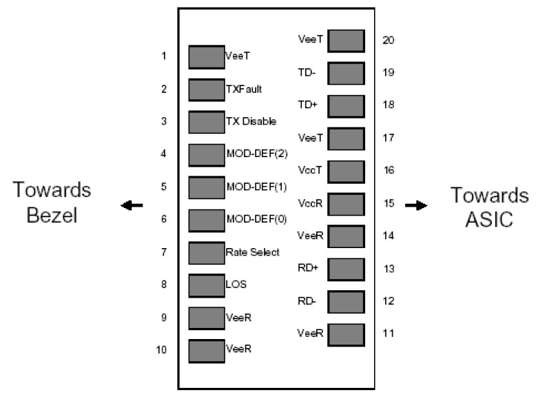
Diagram of Host Board Connector Block Pin Numbers and Name

Pin Description

Pin

Name

Function / Description

1

VeeT

Transmitter Ground

2

TX_Fault

Transmitter Fault Indication (1)

3

TX_Disable

Transmission Disable – Module disables on high or open (2)

4

MOD-DEF(2)

Module Definition 2 – SDA: Serial Data Signal

5

MOD-DEF(1)

Module Definition 1 – SCL: Serial Clock Signal

6

MOD-DEF(0)

Module Definition 0 – LVTTL Low (3)

7

Rate Select

Not Connected – Open Circuit

8

LOS

Receiver Loss of Signal (4)

9

VeeR

Receiver Ground

10

VeeR

Receiver Ground

11

VeeR

Receiver Ground

12

RD-

Inverse Received Data out, Differential LVPECL, AC coupled

13

RD+

Received Data out, Differential LVPECL, AC coupled

14

VeeR

Receiver Ground

15

VccR

Receiver Power

16

VccT

Transmitter Power

17

VeeT

Transmitter Ground

18

TD+

Transmitter Data In, Differential LVPECL, AC coupled

19

TD-

Inverse Transmitter Data In, Differential LVPECL, AC coupled

20

VeeT

Transmitter Ground
Note1: TX Fault is open collector/drain output which should be pulled up externally with a 4.7K~ 10KΩ resistor on the host board to supply <VccT+0.3V or VccR+0.3V. When high, this output indicates a laser fault of some kind. Low indicates normal operation. In the low state, the output will be pulled to <0.8V.
Note2: TX Disable input is used to shut down the laser output per the state table below. It is pulled up within the module with a 4.7K~10KΩ resistor. 1)Low(0~0.8V): Transmitter on; 2)Between(0.8V and 2V): Undefined; 3)High (2.0~ VccT): Transmitter Disabled; 4)Open: Transmitter Disabled
Note3: Mod-DEF 0, 1, 2. These are the module definition pins. They should be pulled up with a 4.7K~10KΩ resistor on the host board to supply less than VccT+0.3V or VccR+0.3V. Mod-DEF(0) is grounded by the module to indicate that the module is present. Mod-DEF(1) is clock line of two wire serial interface for optional serial ID. Mod-DEF(2) is data line of two wire serial interface for optional serial ID.
Note4: LOS (Loss of signal) is an open collector/drain output which should be pulled up externally with a 4.7K~10KΩ resistor on the host board to supply <VccT+0.3V or VccR+0.3V. When high, this output indicates the received optical power is below the worst case receiver sensitivity (as defined by the standard in use). Low indicates normal operation. In the low state, the output will be pulled to <0.8V.

Références

Longueur d’ondes

Distance

Temp.

ATV-8330-262

850nm

0.3km

-10~70°C

ATV-8330-262-E

850nm

0.3km

-40~85°C

FINSAR-FTLF8524P2xNV

Finisar’s FTLF8524P2xNV Small Form Factor (SFP) transceivers

Finisar’s FTLF8524P2xNV Small Form Factor (SFP) transceivers are compatible with the SFP Multi-Sourcing Agreement (MSA). They are compatible with Fibre Channel FC-PI-2 Rev. 7.0. Rate selectable versions are also compatible with Gigabit Ethernet as specified in IEEE Std 802.3. The optical transceiver is compliant per the RoHS Directive 2011/65/EU. See Finisar Application Note AN-2038 for more details. Digital diagnostics functions are available via the 2-wire serial bus specified in the SFP MSA.

  • Up to 4.25 Gb/s bi-directional data links
  • Hot-pluggable SFP footprint
  • Built-in digital diagnostic functions
  • 850 nm Oxide VCSEL transmitter
  • Duplex LC connector
  • RoHS compliant and lead free
  • Up to 500 meter on 50/125 µm MMF, 300 meter on 62.5/125 µm MMF
  • Metal enclosure for lower EMI
  • Single 3.3 V power supply
  • Extended operating temperature range: -20°C to 85°C
  • Tri-rate 1.063/2.125/4.25 Gb/s Fibre Channel
  • 1.25 Gb/s 1000BASE-SX Ethernet (Rate selectable version)
  • Wireless – OBSAI, CPRI
Distance:550 m
Data Rate (max):4.25 Gb/s
Protocol:Optical Gigabit Ethernet Compliant1x Fibre Channel Compliant2x Fibre Channel Compliant
Low End Case Temperature (°C): -20
High End Case Temperature (°C):85
Diagnostics:Digital
Transmitter:VCSEL
Receiver:PIN
Voltage Supply:3.3
Connector:LC
Wavelength:850nm Band

BC-230-PB

BC-230-PB : Testeur Profibus PA : Pour les Zones ATEX et non-ATEX

BC-230-PB

Le testeur PROFIBUS PA ( BC-230-PB) est un outil pratique et indispensable pour les tests de réseaux PROFIBUS PA ( Zone ATEX et non ATEX )

Test du bus PA, facile et rapide

Le  moniteur de diagnostic est un outil polyvalent et indispensable pour la mesure des réseaux Profibus PA. C’est auss un produit ATEX, ce qui en fait un appareil utilisable en zone a risque. Pas de besoin de batterie ni de source électrique externe.

Application universelle pour ce testeur profibus PA ( BC-230-PB )

  • Test du bus physic
  • Verification de la stabilité entre les différents devices
  • Outil universel pour l’installation, la mise en service, la documentation, la maintenance préventive et le diagnostic

Très simple d’utilisation

  • Outstanding ease of use based on display and two function buttons ▪ Clear classification of test results as either OK or BAD
  • Ideal choice even for less experienced users

Test de bus totalement automatique

  • Automatically powered by fieldbus and start of segment testing without operator intervention after attachment to PROFIBUS PA network
  • Information in plain text, if measured data exceeds tolerance limits
  • Measurement of segment voltage as well as average noise and peak noise for three frequency ranges
  • Reliable detection of short circuits between individual signal wires and cable shield
  • Detection of all frame retransmissions and all devices added or dropped during bus operation at field device level
  • Determination of current and lowest signal levels of all devices
  • No PC or notebook needed for testing the bus
  • Internal storage of test data for later transfer to PC
  • Detailed test reports in Microsoft Excel or text format
put voltage:Fieldbus mode: 8 to 32 VDC, USB mode: 4.1 to 5.5 VDC
Max. input current:Fieldbus mode: 10 mA *, USB mode: 30 mA
Power dissipation:Fieldbus mode: max. 320 mW (at 32 VDC), USB mode: max. 165 mW (at 5.5 VDC)
Operating temperature:–20 to +50 °C **
Dimensions:146 x 88 x 28 mm
Weight:378 g
Case material:ABS
DC voltage measurement range:8 to 32 VDC ± 0.5 VDC
Signal level measurement range:0.12 to 2 Vpp ±10% ±0.025 Vpp
LF noise measurement range:50 Hz to 4 kHz, 0 to 1000 mVpp ±15% ±25 mVpp ***
FF noise measurement range:9 kHz to 40 kHz, 0 to 1000 mVpp ±10% ±25 mVpp ***
HF noise measurement range:90 kHz to 350 kHz, 0 to 250 mVpp ±20% ±25 mVpp ***
ConformityCE, FCC
Hazardous area approvalsFM USA and Canada:
—Class I Division 2 Groups A, B, C and D T4
—Class I Zone 2 Group IIC T4
—Class I Division 1 Groups A, B, C and D T4
—Class I Zone 0 and 1 Ex/AEx ia IIC T4
ATEX Ex ia IIC T4
ATEX Ex nL IIC T4
ATEX Ex ic IIC T4
Data transfer to PCVia supplied PC software for Windows 2000, XP and VISTA, Windows 7 (32/64 bit) and USB interface version 1.1 or 2.0
*  In  fieldbus  mode  the BC-230-PB  is powered by the  fieldbus and draws approximately 9.4 mA of current from the segment (depending on bus voltage and ambient temperature).
**  Display update speed is impaired below –10°C.
*** Vpp = Volts peak-to-peak; excessive noise adjacent to the fieldbus frequency (FF) band will prevent the BC-230-PB from reading the fieldbus data and thus reduce functionality.
BC-230-PBDiagnostic Monitor for PROFIBUS PA

Scope of Delivery

HardwareDiagnostic Monitor for PROFIBUS PA (BC-230-PB), connection cables, carrying case
SoftwarePC software (in English) on CD-ROM
DocumentationManual (in English), certificates (in English)

Additional Products and Services

PB-LSZ-CHB3Digital fieldbus leakage current clamp for locating EMC problems, 40 Hz … 1,000 Hz, Min/Max, Data Hold, measuring cables, supplied in handy case

Pour toute demande, nous consulter

Ce produit fait partie de  la famille des « Process automation ». Afin de connaitre notre gamme complete de produits, vous pouvez télécharger notre brochure :  Process Automation.